

OrCAD X - Your all-in-one PCB design tool for first pass success & quick-turn boards. Design faster, smarter, and with confidence. Start your free trial today!
Joined November 2009
- Tweets4.8K
- Following253
- Followers1.3K
- Likes380






Before power-supply PCB sign-off, check return paths, hot-loop inductance, phase margin across input voltage and load, and worst-case voltage stress.
Kirsch Mackey explains: ow.ly/zh5z5108hiU?
#PowerElectronics

15
Brushed DC motors mechanically switch rotor-winding current. BLDC motors electronically sequence stator windings according to rotor position.
Compare motor types:
ow.ly/hnJO5106M5L
#MotorControl #PowerElectronics

65
Rename IO nets to GPIO on one schematic page without changing the others. Then trace cross-page connections with Navigate in Allegro X System Capture.
Part 4 also covers ESP32 regulator and LED wiring.
ow.ly/2Cs85106LTs

2
63
What’s the nastiest convergence problem you’ve solved, and what finally fixed it?
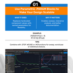
Check out all 10 PSpice simulation tips, including parametric .PARAM blocks, behavioral sources, and automated .MEASURE runs.
Full infographic here 👇 ow.ly/TYe85103rCG
#PCBDesign #PSpice #CircuitSimulation

51
Run the bias point before any other analysis. If the DC operating points are wrong, the AC and transient results won’t mean much.
Full course here 👇 ow.ly/5VFb5103rll
#PCBDesign #PSpice

37
Moving a design from Altium to OrCAD X: file prep, schematic and layout import, library extraction, and cleanup, step by step.
Full guide here 👇 ow.ly/Rfay5103rtH
#PCBDesign #OrCADX

51
PSpice 23.1 Walk-Through: a 4-hour course covering bias point, DC, AC and transient sims, plots, measurements, ABMs, and stress analysis. No prerequisites.
Full course here 👇 ow.ly/5VFb5103rll
#PCBDesign #PSpice

42
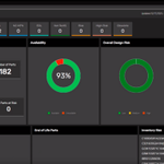
OrCAD X's Live BOM dashboard: data on over 1.6 billion parts, an A-to-D risk grade (A is lowest risk), and alternates with lifecycle status, lead time, cost, and availability trends. Cadence PCB Solutions walks through the full workflow in the blog.
👉 ow.ly/OmBv5101QJT
#PCBDesign

1
44
A probe shows you one node. It can also change the circuit you’re measuring. On high-power boards, some failures live where you can’t probe. Simulation can look there.
Register Here:
#PCBDesign
Register Here: cadencedesign.registration.g…
The catch is trust. A model only earns it if it reproduces the failure you saw on the bench first. After that, you can change one thing at a time (a path, a decoupling choice, a component) and compare candidates before building anything.
That’s the workflow Ted Larson of OLogic covers for a high-power motor controller that kept failing in the lab: why the failure was hard to diagnose, what Sigrity X PowerSI and PSpice showed, and how the team evaluated alternatives before making a hardware change.
When you evaluate a fix before a respin, what convinces you the model is right: a bench correlation, a known-good reference, or a gut check?
#PCBDesign #Webinar

1
64
A signal over a solid power plane couples just like one over ground. So where do you draw the line on referencing high-speed signals to power, and why?
👉 ow.ly/hijg50ZZ57B
#PCBDesign

43
Part three of the How-To Allegro X series released. Adam walks through the whole build: the USB-to-serial page, a logic table, notes, and two 21-pin headers.
👉 ow.ly/sWgO51033ay
#PCBDesign #AllegroX #SchematicDesign

44
Cadence System Design and Analysis retweeted

Before sovereign AI goes live, sites that appear ready on paper can still encounter power, thermal, resilience, or regulatory constraints as plans move closer to reality.
Our new eBook explores how continuous modeling can help teams validate site readiness earlier and make better-informed decisions before key choices are locked in.
Download it here: ow.ly/wFLP5101PGu

Top 10 schematic ERC questions: why power nets read undriven, why valid connections get flagged, why hundreds of violations may be one root cause.
👇ow.ly/K19R5102N6r
#PCBDesign #SchematicDesign #ERC

53
Form, fit, function: how to vet components before the BOM locks. Lifecycle, RoHS, alternates, and risk grades in OrCAD X Live BOM.
👉 ow.ly/OmBv5101QJT
#PCBDesign

52
Myth: more airflow always means better cooling. Reality: air that bypasses the hot parts, or recirculates back to them, does little. Vent placement matters.
Full guide here 👇 ow.ly/cLBe5101OQ6
#PCBDesign #ThermalManagement #Reliability

39
Ted Larson, OLogic: the lab failure was hard to diagnose because traditional debug couldn’t easily show the cause. Simulation exposed behavior that measurement alone didn’t.
Register Here 👇 ow.ly/g1CG5101lmn
#PCBDesign #Webinar

1
43
Part two of the How-To Allegro X series is now available to watch!
👉 ow.ly/JrUA51013mL
#AllegroX #PCBDesign

55
Your preferred part goes end-of-life. What do you check first on the alternate: electrical parameters, footprint, lead time, or lifecycle status?
All easy to do with Live BOM 👉 ow.ly/rSqk5101QVi
#PCBDesign #OrCADX

24
OrCAD X's Live BOM dashboard: data on over 1.6 billion parts, an A-to-D risk grade (A is lowest risk), and alternates with lifecycle status, lead time, cost, and availability trends. Cadence PCB Solutions walks through the full workflow in the blog.
👉 ow.ly/OmBv5101QJT
#PCBDesign

32
At 5 GHz in FR-4, wavelength is about 30 mm. A via fence only shields if spacing stays under λ/10, so under 3 mm. Wider, and the fence is transparent.
👉 ow.ly/hijg50ZZ57B
#PCBDesign

31